News Categories
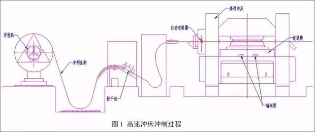
Modern stamping technology is a high and new technology integrating equipment, mould, material and technology. High speed stamping technology is an advanced forming technology developed in recent 20 years. The modern stamping technology of motor stator and rotor iron core parts is to use a multi station progressive die with high precision, high efficiency, long service life and integrating all processes in one die to carry out automatic stamping on the high-speed punch. The stamping process is that after the stamping strip comes out of the coil, it is leveled by the leveling machine, then automatically fed by the automatic feeding device, and then the strip enters the die, It can continuously complete the stamping of blanking, forming, finishing, edge cutting, automatic lamination of iron core, blanking of lamination with twist, blanking of lamination with turn back, etc. until the finished products of iron core parts are transported from the mold, the whole stamping process is automatically completed on the high-speed punch (as shown in Figure 1).

Setting and quantity determination of lamination riveting of motor stator and rotor iron core:
The location of the riveting point of the stator and rotor iron core of the motor shall be determined according to the geometry of the stamping sheet, and considering the electromagnetic performance and application requirements of the motor, whether there is interference in the position of the punch and die insert of the riveting point and the strength of the distance from the edge of the corresponding riveting ejector rod hole of the blanking punch shall be considered on the die. The overlapping riveting points shall be symmetrically and evenly distributed on the iron core. The number and size of overlapping riveting points shall be determined according to the required bonding force between iron core punches, and the manufacturing process of the die must be considered. If there is large angle rotary riveting between iron core punches, the bisection requirements of riveting points shall also be considered
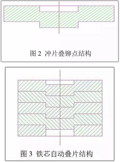
Punch riveting points with a certain geometry on the appropriate parts of the stator and rotor punching plate. The form of riveting points (as shown in Figure 2) is that the upper part is a concave hole and the lower part is convex. Then, when the convex part of the upper punching plate with the same nominal size is embedded into the concave hole of the next punching plate, the "interference" is naturally formed in the tightening ring of the blanking die in the die to achieve the purpose of fastening connection (as shown in Fig. 3). The process of forming the iron core in the die is to correctly overlap the convex part of the upper riveting point with the concave hole of the lower riveting point at the blanking station. When the upper one is under the pressure of the blanking punch, the lower one will produce riveting by virtue of the reaction force generated by the friction between its shape and the die wall.

In this way, through the continuous punching of the high-speed automatic punch, we can get a neat iron core which is arranged next to each other, the burrs are in the same direction and has a certain stacking thickness.